
This is a special kind of bridge which helps us to have a longer span than usual. Usually, the normal span may vary from 30m-40m long but Balanced Cantilever Bridge helps us to get more than 100m long spans without any middle pier/column. That’s why this kind of structure is special to the construction site.
I’m Al-Fattah from Bangladesh, today we are going to discuss this special structure- Balanced Cantilever Team from my work experience at Bangladesh’s first metro rail project- Dhaka Mass Rapid Transit Development Project: Line 06.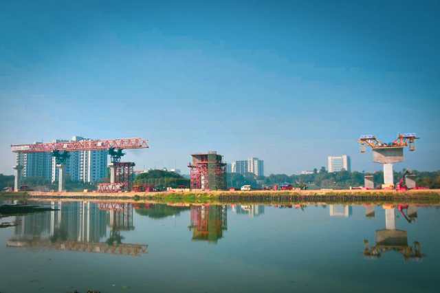
So, What is the Balance Cantilever method for bridge construction?
Balance cantilever is the method that helps us to build bridges consisting of longer spans from 50 m to 250 m without installing any kind of ground support. The bridge can be either Cast in-situ or pre-cast. The basic concept of this construction method is to construct a bridge without installing scaffolding systems under the bridge and complete the superstructure of the bridge by sequentially joining the segments to form a span by post-tensioning and balancing the left and right from each pier using special erection equipment.
Now, Let’s discuss Why we use the balance Cantilever method?
On construction sites, we often find some areas where we can’t maintain the normal span length. Sometimes this span length may increase up to 100 m or more. The site situation doesn’t allow us to use an intermediate pier to shorten the span length. So, how we can complete this span? To complete a span like this, the Balance Cantilever method can be efficient. We can use this method in various site conditions, like:
Irregular and long span lengths,
Congested project sites,
Rough and water terrain,
Rail crossings,
Environmentally sensitive areas etc.
The procedure of cast-in-situ pier segment for Balance Cantilever Bridge:
We can divide the Balance Cantilever method into two steps:
-Construction of cast-in-situ pier segment which we can define as Pier table
-Construction of the rest of the bridge . We can complete this work in two different ways. One is cast in-situ segment construction using form-traveler and another is erection of pre-cast segments to complete the whole bridge.
In this article, we’ll discuss the construction method of the Pier Table along with the pre-cast segment erection method to complete the bridge.
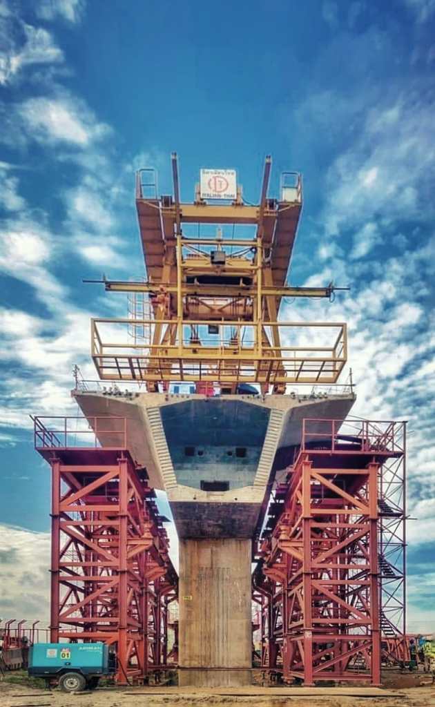
Construction method of Pier-Table for Banalce Cantilever Bridge:
Concrete base for installing ground support:
The pier table we are going to construct has its design and elevation. We’ve to follow the design data in every step of our work. Otherwise, we won’t be able to match the design elevation. To match the elevation, we’ve special ground supports with screw jacks. If we use steel formwork, then we must use steel-framed ground support and if we use plywood formwork, we can use scaffolding as ground support. Whatever we use, we’ve to follow its appropriate instructions and drawings.
Now, before installing ground support, we’ve to make a concrete base for it. So that, all the ground support can have a strong and same level base. Then we’ve to match the ground support elevation with the design. For that, we’ve to use the help of the site survey team. I prefer to take a reference elevation point from the survey team before starting this type of work. So that, We can measure and check if the level is ok or not from that reference point using Water Level in the future. Remember, we’ve to lock all of these ground support with proper locking. We can use Tie-rods, Steel Pipes, and anchor locks, welding steel channels all around the ground as locking.


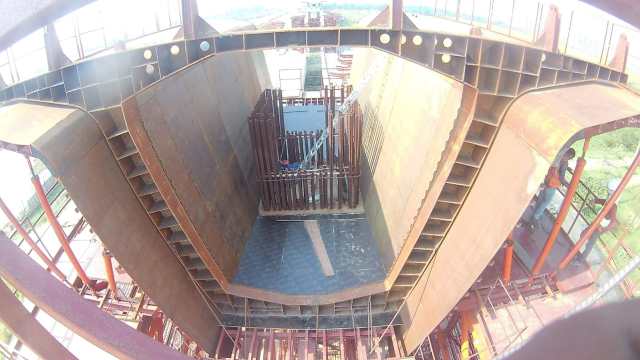
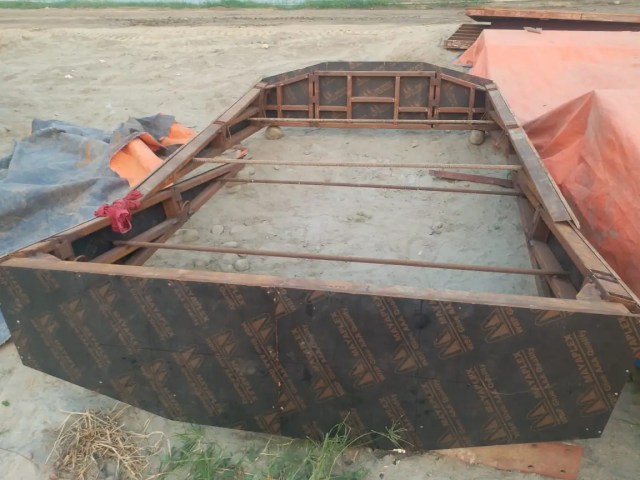
Installation of special frame & Bottom Formwork for Balance Cantilever Bridge:
Our pier table has a special frame for its bottom formwork. We’ve to fix this according to its design elevation using screw jacks. We should make sure that the bottom formworks align with the column centerline. We must check every corner with the design elevation data. If the elevation matches, we can permanently fix the frame and set the bottom formworks.


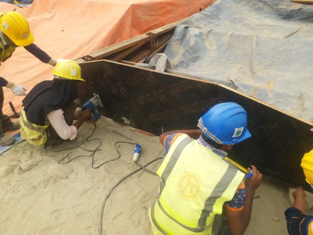
Installation of side and flange Formwork for Balance Cantilever Bridge:
After installing bottom formworks as per the design, we can start installing side formworks. For that, we should check the side formworks bottom elevation with the design and fix an H-beam all along the elevation line, so that we can fix side formworks on it. We fixed the Flange (top slab) formworks with the side formworks. So we must be careful about lifting this whole formwork altogether. We should maintain proper safety precautions during lfting to finish this part of works safely. Don’t worry about the top slab elevation, we can adjust it later.
For your information, We used Rubber Gasket and silicon all along the formworks joint to stop leakage during concrete casting. The formworks must be rust-free, so we should clean the formwork properly before using it.


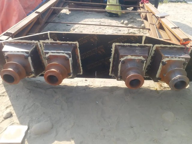
Bulk-Head installation for Balance Cantilever Bridge:
The next step is another critical step in the balance cantilever method. We have to install bulk-heads on two sides of the pier table. It determines the thickness of the sidewall and top slab. We’ve to set these two bulkheads aligned with column and bottom formworks center-line. We should be careful about its elevation and position as all the duct pipes go through it. If its position isn’t right, we can’t fix the duct profile correctly. So, the position and elevation of the bulkheads are very crucial.
Once we fix the elevation and level of the bulkhead perfectly, we can adjust the flange formworks level with it.


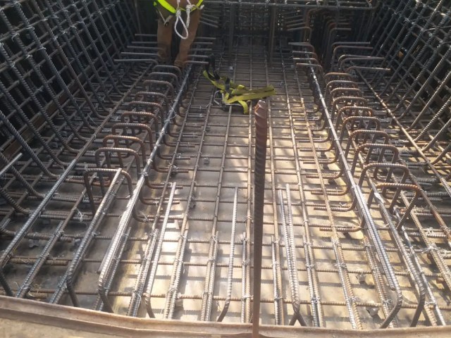
Installation of First part rebar for Balance Cantilever Bridge:
If we can install the side formworks and bulk-head properly, we can start the first part rebar binding. The rebar should be rust-free. We should fix rebars as per the design. Remember to use proper concrete spacer or block to maintain clear cover. The height of the first part should be 1.4 m from the top of the existing column. This measurement can be varied by design in another project.


From my experience, I’ve faced a few problems during fixing rebars as per the design. Sometimes the site conditions won’t allow us to fix rebar as per the design. So we made an FCR (Field Change Request) which included all the rebars we would change to use on-site and submitted to our design team for further review and approval. Remember, this document is very vital for changing any drawing or design on the site.


Steel flat bar fixing for earthing terminal:
The next step is to welding the steel flat bar as per the earthing-bonding drawing. We should carry out the earthing-bonding test after installing the earthing terminal in the required position.
Installation of first layer duct pipe and first part Inner Formwork :
Installation of duct pipe starts after fixing the first layer rebar. We followed a separate drawing that includes all stressing data in this step. One can easily determine the horizontal and vertical values from it. We divided the total duct profile length into some ideal sections to check these values.
Once we fix the first layer duct profiles as per drawing, we can go for fixing our first part inner formwork. Note that, we made this formwork using plywood and steel frame. We fixed anchor boxes and anchor heads with this inner formwork. So we should be very careful about its measurements as the duct profile goes through it. The proper measurements for fixing this can be found in approved drawings.
After fixing inner formwork perfectly, we installed drainage pipes and other utility pipes as per design.


First step Concrete pouring of Balance Cantilever Bridge:
Consultant engineers should check all of the above works from time to time. All of these works are attached so we’ve to check them properly before concreting. Once we find all of these steps area okay, we can go for the first step of concrete pouring.
For the concrete pouring step, we should ensure the concrete quality. Proper vibrating, curing, covering, and rough surface making for next step concrete joints are included in this step. We used External Formwork vibrators along with hand vibrators of different diameters to perform good quality casting works.


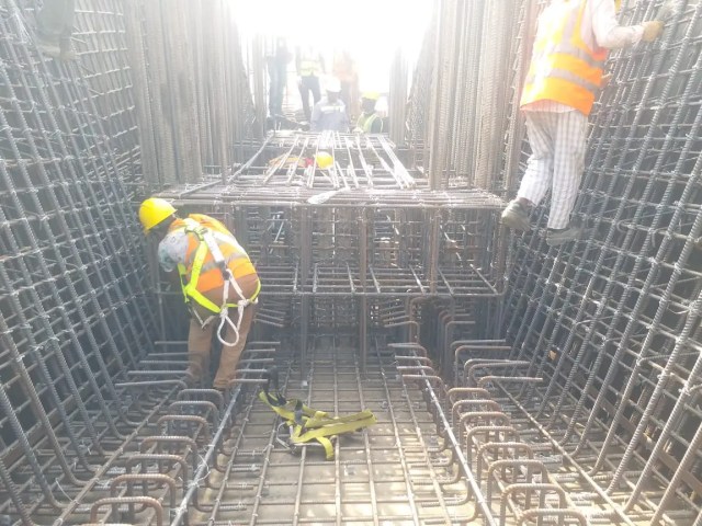
Column Rebar Binding & Column Inner Formwork fixing:
We can start column rebar binding after finishing the first part of concrete pouring. Once we completed the rebar binding of the column, we started fixing the column inner formwork. The Column inner formwork contains anchor boxes and anchor heads for the middle portion duct profile. We should check the elevation of this formwork very carefully. Otherwise, it’ll obstruct with top slab formwork.


Middle Portion Duct profile fixing:
We set the middle portion duct prodiles after fixing the column inner formwork. We should fix these duct profiles as per the approved stressing drawing.


Inner Side Formworks:
After properly fixing the column formwork and middle portion duct profile, side formwork is next. The side formwork will sit on top of the first part inner formwork. We should be careful about the formwork joints. The formworks should be properly cleaned and locked. We should use tie rod locking to lock these formworks perfectly.


Top Formwork fixing:
To install top formwork, we should use two H beams as support and screw jacks to maintain the elevation. We can use plywood to make these formworks. We should check the site condition with the approved drawings. Silicon should be used in between the formworks joint, external tape is another way to prevent leakage during concrete pouring. We should check the top elevation of the top formworks whether it matches with the design elevation or not. If it doesn’t match with the design data, then we can use screw jacks to acquire the expected elevation.


Top Rebar Fixing (Bottom Layer):
We can start fixing the top part rebar after fixing the top formworks. Laying down the bottom part rebars will let us know to start fixing the top part duct pipes.


Duct Profile Fixing:
This is another crucial step in the balance cantilever work procedures. There is a stressing drawing for top part duct profiles which will be followed to fix these duct pipes according to the horizontal and vertical measurements.
we should be careful about welding works or it can damage our profiles.


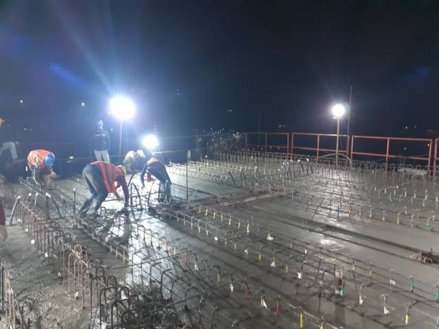
Top Rebar Fixing (Top Layer):
After fixing and checking duct profiles according to the approved drawing, the top layer of the slab rebars can be installed. This part includes the shear rebars also. we should follow the drawing to maintain the Crane holes and drainage pipes. This works also as a part of top rebar bindings.


Final Concrete Pouring:
All of the above works should be checked and approved by consultant engineers. If everything can be found satisfactory, we can go for full and final concrete pouring. Before concrete pouring, we have to apply shutter oil on the formworks body, bonding agent on the previous concrete layer. If we use steel formworks, we shall install external vibrators to ensure proper vibrating. Hand-used vibrators should be used under the proper instructions of the responsible engineers.


Curing, and Covering:
A curing compound should be used all over the concrete surfaces soon as the concrete layer starts to gain its hardness. After applying curing compound all over the concrete surfaces, we should cover it with proper covering materials.


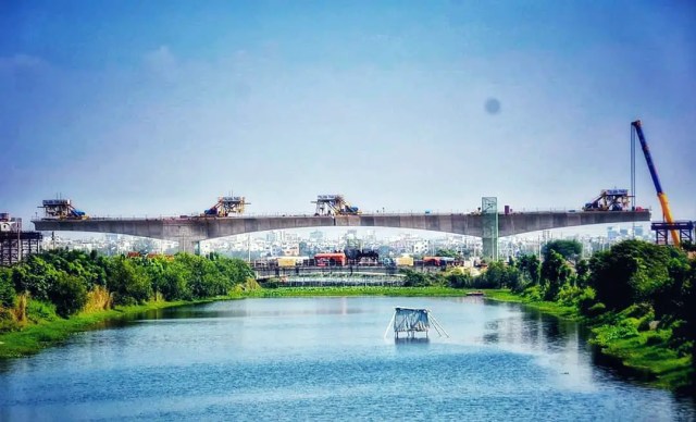
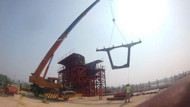
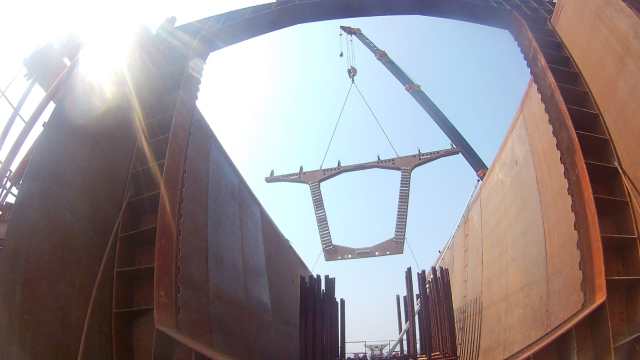
Segment Erection and Stressing Procedure:
After final concrete pouring, we should wait for the lab report of the concrete. As soon as we get the confirmation from the lab, we can start dismantling Formworks. After all of the formworks are removed, we can go for segment erection and stressing works.


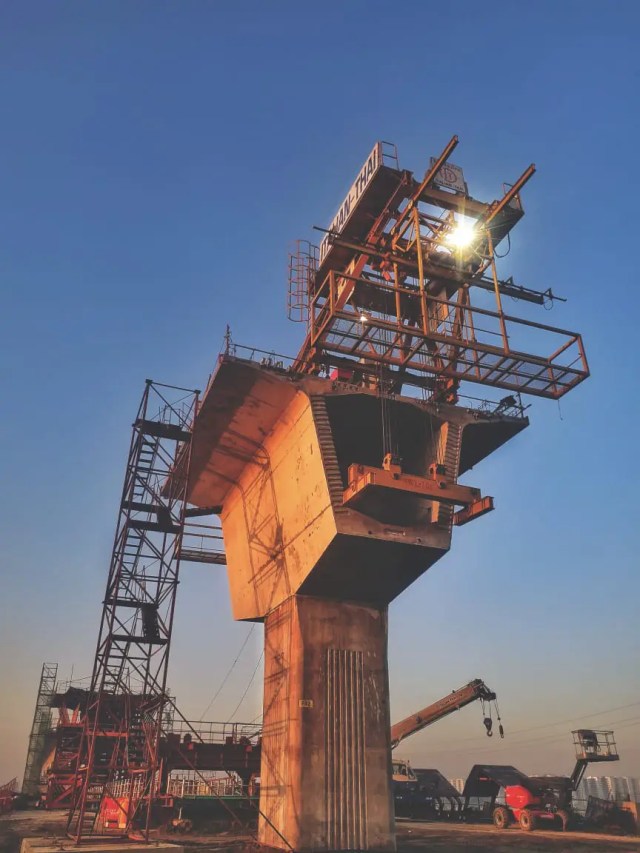
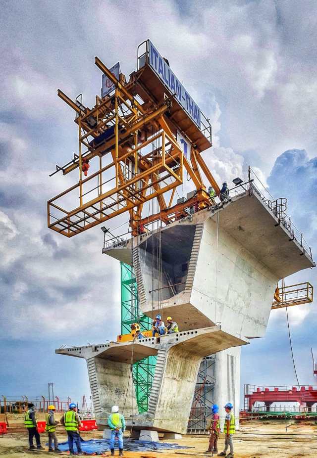
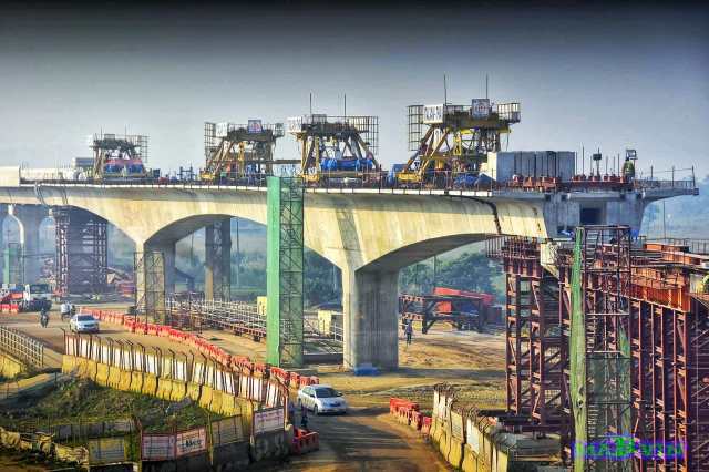
We used Derrick-Crane, which was set up on top of the pier table. Two cranes were set up on the top of the pier table. The erection procedure was to start lifting two segments at a time with balancing among themselves. Two wet joints of 300mm concrete casting were introduced in between the first two segments and the pier table. After finishing doing all these, stressing works can be started for the first two pre-cast segments and the pier table. Once done with the first two segments, we can move to lift another two pre-cast segments. A sequence of lifting and stressing is followed all over the procedure to complete the whole span.

Document Reference:
All document reference are taken from Dhaka Metro Rail Project, Bangladesh:
CS-CP6-VSB-C06-00022
CS-CP3-VBS-C03-00037
ITD/CAL/CP03-04/ALL/TE/0011 Rev.02
CS-BO3-VSB-CO4-00144


Very helpful for construction Engineers 👌
Thank you brother ❤️
Thank you for the valuable information, I really appreciate your endeavors.
Thank you brother ❤️